Typical Components of a Photovoltaic Interconnected System:
Solar Panels
A module or array can convert about 10% of the available sunlight to usable electricity. A module is an assembly of individual Photovoltaic cells which produce approximately 0.5 volts being wired in series and parallel to produce the specified voltage and current. Module performance is described by the following specifications as an example:

Nominal power [Wp] Pmpp: 230 watts
Sorting tolerance: -0 %
Voltage at nominal power [V] Umpp: 30.0 volts
Current at nominal power [A] Impp: 7.66 amps
Open-circuit voltage [V] Uoc: 36.9 volts
Short-circuit current [A] Isc: 8.33 amps
1 The electrical data applies to standard test conditions (STC):
Irradiance at the module level of 1,000 W/m2, spectrum AM 1.5 and a cell temperature of 25°C.
The rated power may only vary by ±4% and all other electrical parameters by ±10%.
Definitions of above Terms
Standard Test Conditions - 1000 watts/square meter; 25 degree C or 77 degree F
Open Circuit voltage (Voc) - Maximum potential voltage generated when no current is being drawn from the module
Short Circuit Current (Isc) - maximum current output by the module when the output wires are shorted together
Maximum Power Point Voltage and Current (Vmp and Imp) - maximum power transfer from the module to the electrical load based on operating conditions such as temperature and sunlight intensity.
Solar Array Mounting Systems:
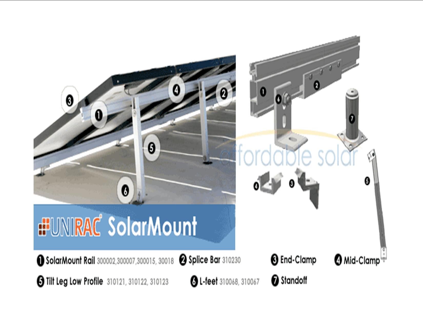
The purpose of the mounting system is to securely fasten the array to a structure such as the roof of a building. The modules must not be twisted or physical distorted in the process. Adequate air circulation around the modules is necessary limit the temperature rise of the panels in sunlight. The efficiency of the array decreases as the temperature increases. All wiring to the modules must be of an insulation type to handle the ambient heat.

The above illustration is of a typical roof mounting system with adjustable tilt angle.
Inverters
The fundamental purpose of an inverter is to change direct current (DC) from the Photovoltaic modules and batteries, if used, to alternating current (AC). Alternating current is the standard electricity available from power utilities and used throughout residential and commercial facilities. To convert DC to AC the DC must be “chopped up” and manipulated (filtered) to approximate a sine wave. With the advent of sophisticated electronics, inverters can now produce a waveform which approximates a true sine wave. Inexpensive inverters that produce a square wave or modified sine wave output must not be used when interconnecting with a power utility company. Inverters for interconnecting must meet Underwriters Laboratory specification UL 1741 and IEEE Standard 1547. Many of the available Inverters have a battery charger built in that can be activated to charge batteries during normal operation if batteries are used as an emergency backup source during a power outage. In addition, an automatic transfer switch is used in conjunction with supplying electrical power to the emergency or backup load distribution panel through the utility connection or inverter.
Solar Charge Controllers
A Solar Charge Controller is the heart of a solar electric system as it is the bridge between the solar panels and the batteries if they are used in the system. The charge controller takes the DC power from the solar panels and adjusts the voltage level and current rate at which electric charge is added to batteries based on the battery voltage. It prevents overcharging and over voltage, which can reduce battery performance or lifespan, and may pose a safety risk. Charge controllers may also monitor battery temperature to prevent overheating. Simple charge controllers stop charging a battery when they exceed a set high voltage level, and re-enable charging when battery voltage drops back below that level. When batteries are not used or required by the inverter, the charge controller regulates the voltage into the inverter system.
Safety Disconnects
Safety Disconnect switches are utilized to sectionalize the system for maintenance and repair. They must have the proper Underwriter’s Laboratory Listing for the voltage and current type. These switches are not to be used to disconnect an electric load in use.
Circuit breakers are inserted in the system at strategical locations to protect wiring and devices from dangerous currents flowing because of faults and short circuits in the system. The circuit breakers must have the proper Underwriter’s Laboratory Listing for the voltage and current type. Circuit Breakers can be used for switching electrical loads.
Author: William D. Wright, PE
NABCEP - Certified PV Installer
bwright@powerquestglobal.com
